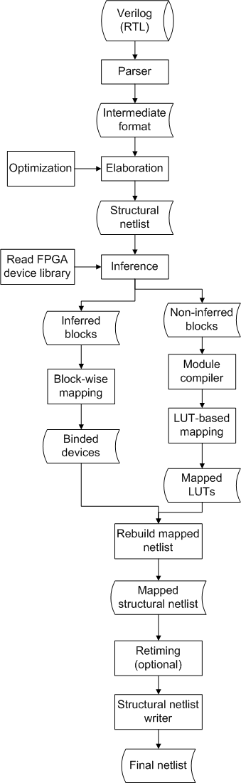
Figure 1. General RTL synthesis flow
Having obtained the IF, the next step is Elaboration, which is to translate the behavior description in Verilog language to structural description. For example, certain statements such as condition statement (indicated by keyword if/case) and loop statement (indicated by keyword for/while) are not interpretable by hardware and must be translated to corresponding structural description. Here condition statement could be translated to one or more MUXes and loop statements should firstly be unrolled and then translated to corresponding structural description. Note that the elaboration procedure is technology independent. After elaboration, a (technology-independent) structural netlist is generated.
During Elaboration, a set of Optimizations should be performed, which has been shown as the main distinguisher of the qualities between different RTL synthesizers. The common optimizations are
-
Arithmetic optimization
-
Multipliers and additions can be shrunk through constant propagation.
-
Replacing ''0'' low order constant inputs to an adder with a wire, and similarly, removing most significant ''0'' constant multiplier inputs.
-
Implementing A+B+1 in one adder using the carry-in signal.
-
-
Finite State Machine (FSM) optimization
-
FSM detection
-
One-hot re-encoding FSM
-
-
MUX collapsing
Device Inference is the next step, which is highly related to a specific FPGA device library. Different FPGA devices and families have different heterogeneous programmable logics, for instance, the implementation capabilities of the DSP blocks in Altera Stratix II and XIlinx Virtex IV are different. Despite those difference, we seek a general implementation in our RTL synthesis system, for which we assume the following heterogeneous logics exist and should be taken care of during inference
-
Memory blocks
-
Arithmetic elements, such as multipliers and adders
-
Macro-gates, such as AND2, OR2 gates
-
DSP blocks, which can implement various even complicated arithmetic operations
It is necessary to find a way to detect each of the above logics from the technology-independent netlist. The cut-based technology mapping is no longer universal since the number of inputs of a DSP unit could be huge (more than 10) and there are multiple outputs of a DSP unit. In practice, people select a seek node (e.g., a multiplier, '*') and perform the local search trying to find a matched pattern which can be implemented by a DSP device.
After inference, part of logics (inferred blocks) are mapped to certain heterogeneous logics in FPGA library while the others (non-inferred blocks) are unmapped. For those inferred blocks, a block-wise mapping is performed to do i) sanity-check ii) simple duplication to satisfy the I/O constraints. For those non-inferred blocks, such as a comparer operator ('>'), a module compiler is needed to implement them as basic logic elements (e.g., AND-INVERTER), which will be further mapped to LUTs or dedicated macro-gates (LUT-based mapping). When two types of logics (inferred blocks and non-inferred blocks) are mapped, the netlist needs to be rebuilt to correct the port connections.
A retiming procedure or other optimization could be performed after the mapping procedure.
To interface with other CAD tools for back-end flow, a structural netlist writer is needed to produce various netlist format, such as structural Verilog, EDIF (needed by Altera Quartus) and XNF (needed by Altera ISE). To inform the back-end tool about the synthesis results, Library Parameterized Modules (LPMs)/Library Templates can be used so that Quartus/ISE will bind to an implementation on the FPGA whether that be a hard or soft implementation.
The behavior of the finalized netlist should be verified. One way for the verification is to write a simple testbench to tie the primary outputs of the synthesized netlist and the original netlist with a set of XOR gates and perform the simulation by random input vectors. No logic '1' should appear if the synthesis tool works correctly.